Basic Information

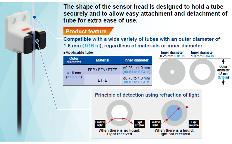
For use with ø1.6 mm (ø1/16 in) tubes
Optical Bubble Sensor
Adjustment has never been easier!

Tube holding mechanism
The original design ensures perfect fit of a tube without impeding the flow of liquid. Also compatible with tubes in inch size.
Simply attach the sensor with your hand!
Hassle-free one-touch attachment without using tools!
Fingertip size
Allows for installation in a narrow space.
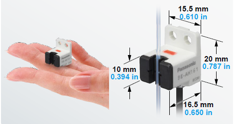
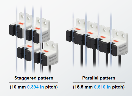
Allows for close proximity attachment
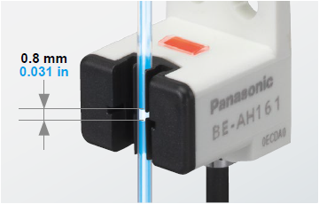
Detection of 0.8 mm 0.031 in air gap
0.8 mm 0.031 in air gaps are reliably detected by optical technology at a response time of 80 μs.
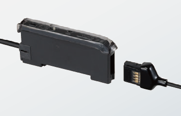
e-CON connectivity
The product is equipped with an e-CON connector, a type of connectors commonly used for the connection of sensors, thus significantly reducing the manhours required for cumbersome wiring.
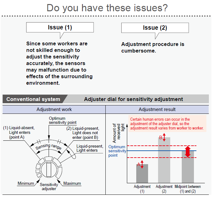
The sensor sensitivity can be adjusted easily by anyone according to tube conditions.


Cell sorter
- Detection of air bubbles in the sample liquid

Genetic testing equipment
- Detection of air bubbles before dispensing the liquid onto microchannel chips

Gene amplification and extraction equipment
- Detection of absence of reagent
- Detection of air bubbles in the liquid delivered by pump

Order guide
Sensor head
| Type | Appearance | Applicable tube | Model No. |
|---|---|---|---|
| Unit compatible with tubes with 1.6 mm (1/16 in) outer diameter |  | Transparent resin tube (Equivalent to PFA) • Material: FEP / PFA / PTFE / ETFE • Outer diameter: ø1.6 mm (ø1/16 in) • Inner diameter: <For FEP / PFA / PTFE> ø0.25 to 1.0 mm (ø0.01 to 0.04 in) <For ETFE> ø0.75 to 1.0 mm (ø0.03 to 0.04 in) | BE-AH161 |
Sensitivity adjustment unit
| Type | Appearance | Model No. | Output |
|---|---|---|---|
| Cable type |  | BE-AC101 | NPN open-collector transistor |
| BE-AC101P | PNP open-collector transistor |
Model No. when ordering accessories additionally
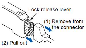
・CN-EP1 (sensor head connector) [5 pcs. per set] (Note)
Note: One head sensor connector is provided with the product.
Option
| Designation | Appearance | Model No. | Description |
|---|---|---|---|
| Sensitivity adjustment unit mounting bracket |  | MS-DIN-2 | Dedicated mounting bracket for sensitivity adjustment unit |
Specifications
| Model No. | BE-AH161 | |
|---|---|---|
| Applicable regulations | CE Marking(EMC Directive, RoHS Directive) | |
| Sensing object | Liquid (Note 2) | |
| Applicable tube type (Note 3) | Transparent resin tube (equivalent to PFA) | |
| Applicable tube dia. (Note 3) | Outer dia. | ø1.6 mm ±0.025 mm ø1/16 in ±0.001 in |
| Inner dia. | <For FEP / PFA / PTFE> ø0.25mm -0.025mm to ø1.0mm +0.025mm ø0.01 in -0.001 in to ø0.04 in +0.001 in <For ETFE> ø0.75 mm -0.025 mm to ø1.0 mm +0.025 mm ø0.03 in -0.001 in to ø0.04 in +0.001 in | |
| Detectable air gap | 0.8 mm 0.031 in or more (Note 4) | |
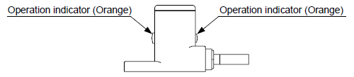
| Operation indicator | Orange LED (lights up with absent liquid) | |
| Environmental resistance | Protection | IP40 (IEC) |
| Ambient temperature (Note 5) | -10 to +55 ℃ +14 to +131 ℉ (No dew condensation or icing allowed), Storage: -20 to +70 ℃ -4 to +158 ℉ | |
| Ambient humidity | 35 to 85 % RH, Storage: 35 to 85 % RH | |
| Ambient illuminance | Fluorescent light: 1,000 ℓx or less at the light-receiving face | |
| Voltage withstandability | 1,000 V AC for one min. between all supply terminals connected together and enclosure | |
| Insulation resistance | 20 MΩ or more, with 250 V DC megger between all supply terminals connected together and enclosure | |
| Vibration resistance | 10 to 150 Hz frequency, 0.75 mm 0.030 in double amplitude or maximum acceleration 49 m/s2, in X, Y and Z directions for two hours each | |
| Shock resistance | 100 m/s2 acceleration in X, Y, and Z directions three times each | |
| Emitter element | Infrared LED (Peak emission wavelength: 855 nm 0.034 mil, non-modulated) | |
| Material | Enclosure: PBT, Tube holder: Polyamide, Indicator: Polycarbonate | |
| Cable | 0.09 mm2 4-core cabtyre cable 1 m 3.281 ft (Provided with a connector for the connection of sensitivity adjustment unit) | |
| Weight | Net weight: 15 g approx., Gross weight: 25 g approx. | |
Notes:
1) Where measurement conditions have not been specified precisely, the conditions used were an ambient temperature of +23 ℃ +73.4 ℉.
2) Sensing is affected by dirt or residues adhered to the inner wall of the tube. Before using the product, be sure to confirm correct detection using actual tube, sensing liquid and equipment.
Sensing object e.g.: Water (Tap water), Pure water, Ethanol, PBS, Isopropanol, Trypsin EDTA (with Phenol Red)
3) When using a tube out of specifications or it doesn’t have a smooth surface, please test sensing on the actual machine before use.
4) Sensing air gap refers to the width of an air bubble formed in the entire area of the inner diameter of the tube. Please note that this product cannot sense very small air bubbles or water drops. Refer to the figure 1 and 2.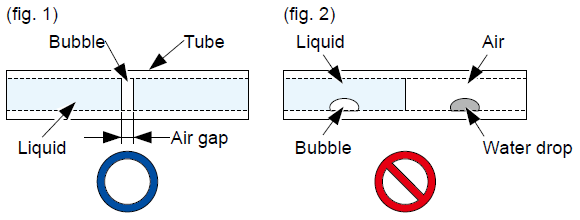
5) Liquid being detected should also be kept within the rated ambient temperature range.
Sensitivity adjustment unit
| Model No. | NPN output | BE-AC101 |
|---|---|---|
| PNP output | BE-AC101P | |
| Applicable regulations | CE Marking(EMC Directive, RoHS Directive) | |
| Supply voltage | 5 to 24 V DC ±10% Ripple P-P 10% or less | |
| Current consumption | 900 mW or less | |
| Output | <NPN output type> NPN open-collector transistor • Maximum sink current: 16 mA • Applied voltage: 30 V DC or less (between output and 0V) • Residual voltage: 1 V or less (sink current at 16 mA) <PNP output type> PNP open-collector transistor • Maximum source current: 16 mA • Applied voltage: 30 V DC or less (between output and +V) • Residual voltage: 2 V or less (source current at 16 mA) | |
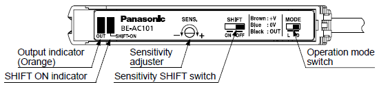
| Output operation | Light-ON (Liquid-absent-ON) / Dark-ON (Liquid-present-ON) selectable (Note 2) | |
| Short-circuit protection | Incorporated | |
| Response time (Note 3) | Bubble detected: 80 μs or less, Liquid detected: 200 μs or less | |
| Output indicator | Orange LED (lights up when the output is ON) | |
| SHIFT ON indicator | Green LED (lights up when sensitivity SHIFT switch is ON) | |
| Sensitivity adjuster (Note 4) (Note 5) | 18-turn potentiometer | |
| Sensitivity SHIFT switch (Note 6) | Shifts the set sensitivity level | |
| Protection circuits | Power supply reverse polarity protection, Output reverse polarity protection | |
| Environmental resistance | Ambient Temperature | -10 to +55 ℃ +14 to +131 ℉ (No dew condensation or icing allowed), Storage: -20 to +70 ℃ -4 to +158 ℉ |
| Ambient humidity | 35 to 85 % RH, Storage: 35 to 85 % RH | |
| Voltage withstandability | 1,000 V AC for one min. between all supply terminals connected together and enclosure | |
| Insulation resistance | 20 MΩ or more, with 250 V DC megger between all supply terminals connected together and enclosure | |
| Vibration resistance | 10 to 150 Hz frequency, 0.75 mm 0.030 in double amplitude or maximum acceleration 49 m/s2, in X, Y and Z directions for two hours each | |
| Shock resistance | 100 m/s2 acceleration in X, Y, and Z directions three times each | |
| Material | Enclosure: PBT, Case cover: Polycarbonate | |
| Cable | 0.2 mm2 3-core cabtyre cable 1 m 3.281 ft long | |
| Cable extension (Note 7) | Extension up to total 100 m 328.084 ft is possible with 0.3 mm2, or more, cable. | |
| Weight | Net weight: 35 g approx., Gross weight: 80 g approx. | |
Notes:
1) Where measurement conditions have not been specified precisely, the conditions used were an ambient temperature of +23 ℃ +73.4 ℉.
2) Operation mode switch is set to Dark-ON (Liquid-present-ON) by default.
3) The indicated response time is a typical value in the use of a compatible tube. Note that actual response time varies depending on the size, light transmission degree, surface condition, etc. of the tube used.
4) To adjust the sensitivity, turn the sensitivity adjuster slowly using a slotted screwdriver (not provided). Turning the adjuster with excessive force can cause malfunction. The sensitivity adjuster is a multi-rotational variable resistor. When the adjuster is turned fully to one side, the clutch mechanism allows the dial to rotate freely with a clicking sound. The clicking sound may not be heard or very low to notice.
5) If the output indicator does not light when the sensitivity adjuster is turned, check the tube installation condition. If the air gap is not correctly detected during the replacement of the tube, adjust the sensitivity adjuster again.
6) The sensitivity SHIFT switch is set to OFF by default.
7) Confirm that the power supply voltage at the end of cable is more than 4.5 V when using an extension of over 20 m 65.617 ft.
Dimensions
(Unit: mm in)
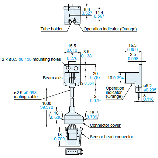
BE-AH161
Sensor head
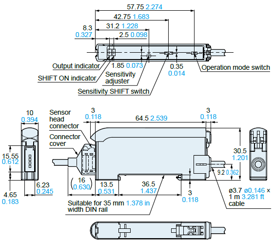
BE-AC101
BE-AC101P
Sensitivity adjustment unit
MS-DIN-2
Sensitivity adjustment unit mounting bracket (optional)
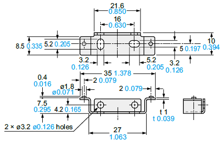
Material: Cold rolled carbon steel (SPCC) (Uni-chrome plated)
I/O Circuit and Wiring diagrams
BE-AC101
NPN output type
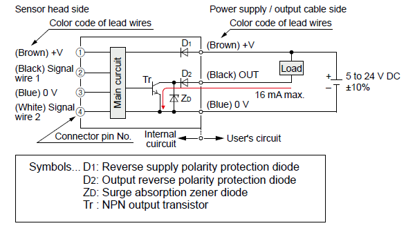
BE-AC101P
PNP output type
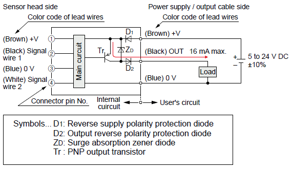
- This product is designed to satisfy the specifications when it is used together with the sensor head BE‑AH161 and sensitivity adjustment unit BE-AC101(P). If the product is used in combination with other units, it may not only fail to meet the specifications but also malfunction in some cases. Be sure to use the product together with the specified units.
Part description
Sensor head
Sensitivity adjustment unit
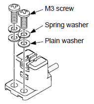
Mounting
Sensor head
<Installation of sensor head>
- When securing the main body with screws, use M3 screws with tightening torque of 0.5 N∙m or less. Use plain washers of small round type (ø6 mm ø0.236 in).
- Please prepare M3 screws, spring washers, and plain washers separately.
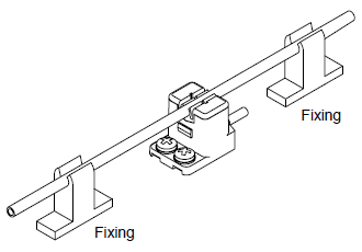
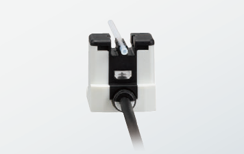
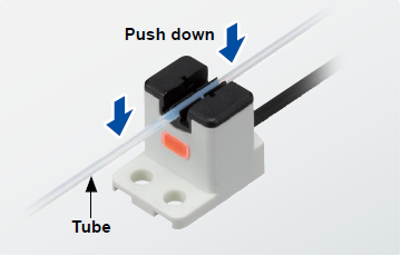
<Attachment of tube>
- Push the tube (PFA or equivalent) into the tube holder as shown in the diagram on the right for the secure attachment of the tube.
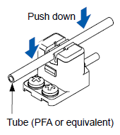
- Be sure to mount the tube in close contact with the sensing element. Otherwise, the product may malfunction. If the tube is brought up or slips off, take additional measures such as attaching an auxiliary fitting to fix the tube.
- Please prepare the auxiliary fitting for fixing the tube separately.