Basic Information

“Ease of use” evolves to the next generation.

Features
Overwhelmingly easy to understand, Organic EL display
The clear, high-visibility flat panel ensures easy operation to reduce setting time and minimize setting errors. It contributes to improved efficiency on the production site.

Enables intuitive operation without referring to the manual
[Reduces setting time] [Minimizes setting errors]

Compact body
The compact body can be easily mounted to small equipment and robotic hands with limited installation spaces.

[New function] Smart limit teaching
Simultaneous execution of teaching and circumvention of saturation
Teaching is executed only with two pushes of a button, and this also achieves circumvention of saturation simultaneously.
There is no need for separate adjustment of the light emission amount, thus contributing to reduction of setting man-hours.
* Only when limit teaching is used

Incident light intensity adjustable in 100 increments
The incident light intensity can be varied in 100 steps to allow flexible and precise adjustment of incident light intensity even when the incident light becomes saturated due to installation in a close distance or during detection of a transparent or very small workpiece, thus realizing stable detection.
Detection of metal wire

Detection of transparent sticker on transparent sheet
Alternate frequency interference prevention function
In the case the fibers are arranged side by side, mutual interference can be prevented by setting different light emission frequencies (4 settings).

* Response time varies depending on light emission frequencies.
* When the alternate frequency interference prevention function is used, up to four fiber head units can be mounted in contact with each other.
Zero-set function
When a reflective type fiber is used, offsetting the incident light intensity to "0" with no workpiece present enables confirmation of only the change caused by the detected object.
When multiple amplifiers are mounted side by side, all displayed values can be set to "0."

Equipped with three types of timer function
A variety of timer control operations can be carried out only by fiber sensors.

Timer period setting range: 1 to 9,999 ms, in 1-ms increments (default setting: 1 ms)
Display and indicator can be set to OFF.
Since the digital display and large output indicator can stay turned off during use, the FX-250 series is suitable for use with equipment that can be affected by light or heat.

Stable detection over long periods and short periods
Stabilization of light emission amount
The built-in APC circuit stabilizes the short-time fluctuation of the light emission amount at the time of power on and the four-element light emitting diode ensures stable emission over long periods.

■ APC circuit
When power is turned on or when the temperature changes, the sensor's light emission amount fluctuates and causes instability of output. To solve this problem, the APC circuit controls the light emission amount to ensure short-term emission stability.
■ Four-element light emitting diode
When a conventional LED operates for a long period of time, the LED becomes damaged due to heat or the light intensity decreases due to oxidation. The four-element light emitting diode suppresses degradation of the light emitting element to the maximum extent and ensures long-term emission stability.
Order guide
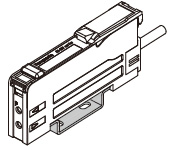
Amplifier
| Appearance | Model No. | Emitting elemen | Output |
|---|---|---|---|
 | FX-251-C2 | Red LED | NPN open-collector transistor |
| FX-251P-C2 | PNP open-collector transistor |
End plates
End plates are not supplied with the amplifier. Please order them separately when the amplifiers are mounted in cascade.
| Appearance | Model No. | Description |
|---|---|---|
 | MS-DIN-E | When an amplifier moves depending on the way it is installed on a DIN rail, these end plates clamp amplifiers into place on both sides. Make sure to use end plates when connecting multiple amplifiers together. [Two pcs. per set] |
Option
| Designation | Model No. | Description |
|---|---|---|
| Amplifier mounting bracket | MS-DIN-2 | Mounting bracket for amplifier |
Amplifier mounting bracket
MS-DIN-2
Others
Please refer to "Fiber Options" for details of fiber lenses and other options.
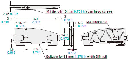
Dimensions
- Unit: mm in
FX-251-C2 FX-251P-C2
Amplifier

MS-DIN-2
Amplifier mounting bracket (Optional)
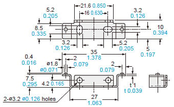
Material: Cold rolled carbon steel (SPCC) (Uni-chrome plated)
MS-DIN-E
End plate (Optional)
Material: Polycarbonate
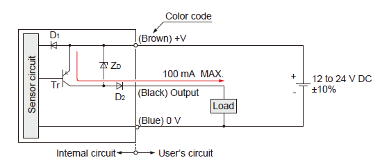
Circuit / Wiring
FX-251-C2
I/O circuit diagram

Symbols…
D1:Reverse supply polarity protection diode
D2:Reverse output polarity protection diode
ZD:Surge absorption zener diode
Tr:NPN output transistor
Wiring diagram

FX-251P-C2
I/O circuit diagram
Symbols…
D1:Reverse supply polarity protection diode
D2:Reverse output polarity protection diode
ZD:Surge absorption zener diode
Tr:PNP output transistor
Wiring diagram

Square Head Fiber
■Thru-beam type(one pair set)
| Type | Model No. | Sensing range(mm in)(Note1) | |||||
|---|---|---|---|---|---|---|---|
| STD | H-PWR | LONG | FAST | H-SPD | |||
| Square head | M3 | FT-R31 | 270 10.630 | 1,000 39.370 | 440 17.323 | 160 6.299 | 55 2.165 |
| M4 | FT-R43 | 720 28.436 | 3,000 118.110 | 1,100 43.307 | 430 16.929 | 130 5.118 | |
| FT-R41W | 800 31.496 | 3,200 125.984 | 1,400 55.118 | 460 18.110 | 130 5.906 | ||
| FT-R42W | 2,200 86.614 | 3,600 141.732 (Note2) | 3,500 137.795 | 1,300 51.181 | 460 18.110 | ||
| FT-R44Y | 720 28.346 | 3,000 118.110 | 1,100 43.307 | 430 16.929 | 130 5.118 | ||
| M6 | FT-R60Y | 2,100 82.677 | 3,600 141.732 (Note2) | 3,600 141.732 (Note2) | 1,260 49.606 | 400 15.748 | |
Note1:Note that sensing range of the free-cut type fiber may be reduced by 20 % max. depending upon how the fiber is cut.
Note2:The fiber cable length practically limits the sensing range.
■Reflective type
| Type | Model No. | Sensing range(mm in) (Note1)(Note2) | |||||
|---|---|---|---|---|---|---|---|
| STD | H-PWR | LONG | FAST | H-SPD | |||
| Square head | M3 | FD-R35G | 130 5.118 | 455 17.913 | 185 7.283 | 65 2.559 | 20 0.787 |
| FD-R32EG | 45 1.772 | 170 6.693 | 92 3.622 | 30 1.181 | 9 0.354 | ||
| FD-R34EG | 38 1.496 | 130 5.118 | 70 2.756 | 23 0.906 | 7 0.276 | ||
| FD-R33EG | 19 0.748 | 84 3.307 | 33 1.299 | 11 0.433 | 3 0.118 | ||
| M4 | FD-R41 | 210 8.268 | 710 27.953 | 320 12.598 | 100 3.937 | 34 1.339 | |
| M6 | FD-R61Y | 280 11.024 | 990 38.976 | 435 17.126 | 160 6.299 | 50 1.969 | |
Note1:Note that sensing range of the free-cut type fiber may be reduced by 20 % max. depending upon how the fiber is cut.
Note2:The sensing range is specified for white non-glossy paper.
For details of Square Head Fiber, refer to product information page.
>>Go to "Square Head Fiber"
Super Quality
■Thru-beam type (one pair set)
| Type | Model No. | Sensing range(mm in) | |||||
|---|---|---|---|---|---|---|---|
| STD | H-PWR | LONG | FAST | H-SPD | |||
| Threaded | M3 | FT-30 | 400 15.748 | 1,350 53.150 | 650 25.591 | 210 8.268 | 75 2.953 |
| M4 | FT-40 | 1,200 47.244 | 3,600 141.732 (Note) | 1,700 66.929 | 530 20.866 | 190 7.480 | |
| Cylindrical | ø1.5 | FT-S20 | 400 15.748 | 1,350 53.150 | 650 25.591 | 210 8.268 | 75 2.953 |
| ø3 | FT-S30 | 1,200 47.244 | 3,600 141.732 (Note) | 1,700 66.929 | 530 20.866 | 190 7.480 | |
Note:The fiber cable length practically limits the sensing range.
■Reflective type
| Type | Model No. | Sensing range(mm in) (Note1) | |||||
|---|---|---|---|---|---|---|---|
| STD | H-PWR | LONG | FAST | H-SPD | |||
| Threaded | M3 | FD-30 | 160 6.299 | 600 23.622 | 250 9.843 | 80 3.150 | 25 0.984 |
| M4 | FD-40 | 160 6.299 | 600 23.622 | 250 9.843 | 80 3.150 | 25 0.984 | |
| M6 | FD-60 | 520 20.472 | 1,550 61.024 | 740 29.134 | 260 10.236 | 90 3.543 | |
| Cylindrical | ø3 | FD-S30 | 160 6.299 | 600 23.622 | 250 9.843 | 80 3.150 | 25 0.984 |
Note1:The sensing range is specified for white non-glossy paper.
For details of Super Quality Fiber, refer to product information page.
>>Go to "Super Quality Fiber"
Threaded Type
■Thru-beam type (one pair set)
| Type | Model No. | Sensing range(mm in) (Note1) | ||||||
|---|---|---|---|---|---|---|---|---|
| STD | H-PWR | LONG | FAST | H-SPD | ||||
| Threaded | M3 | FT-31 | 315 12.402 | 1,350 53.150 | 550 21.654 | 210 8.268 | 70 2.576 | |
| FT-31W | 260 10.236 | 990 38.976 | 440 17.323 | 150 5.906 | 53 2.087 | |||
| FT-32 | 3,000 118.110 | 3,600 141.732 (Note2) | 3,600 141.732 (Note2) | 1,600 62.992 | 580 22.835 | |||
| M4 | FT-43 | 1,400 55.118 | 3,600 141.732 (Note2) | 2,100 82.677 | 770 30.315 | 240 9.449 | ||
| FT-42 | 1,130 44.488 | 3,600 141.732 (Note2) | 1,600 62.992 | 530 20.866 | 190 7.480 | |||
| FT-42W | 800 31.496 | 3,300 129.921 | 1,400 55.118 | 490 19.291 | 160 6.299 | |||
| FT-45X | 1,200 47.244 | 1,600 62.992 (Note2) | 1,600 62.992 (Note2) | 630 24.803 | 200 7.874 | |||
| Elbow | FT-R40 | 930 36.614 | 3,600 141.732 (Note2) | 1,500 59.055 | 500 19.685 | 160 6.299 | ||
| M14 | Long range | FT-140 | 19,600 771.654 (Note2) | 19,600 771.654 (Note2) | 19,600 771.654 (Note2) | 16,000 629.921 | 6,300 248.031 | |
Note1:Note that the sensing range of the free-cut type fiber may be reduced by 20 % max. depending upon how the fiber is cut.
Note2:The fiber cable length practically limits the sensing range.
■Reflective type
| Type | Model No. | Sensing range(mm in) (Note1)(Note2) | ||||||
|---|---|---|---|---|---|---|---|---|
| STD | H-PWR | LONG | FAST | H-SPD | ||||
| Threaded | M3 | FD-31 | 125 4.921 | 515 20.276 | 220 8.661 | 80 3.150 | 25 0.984 | |
| FD-31W | 80 3.150 | 330 12.992 | 140 5.512 | 45 1.772 | 12 0.472 | |||
| FD-32G | 200 7.874 | 650 25.591 | 270 10.630 | 95 3.740 | 27 1.063 | |||
| FD-32GX | 200 7.874 | 630 24.803 | 360 14.173 | 100 3.937 | 30 1.181 | |||
| FD-34G | 90 3.543 | 330 12.992 | 135 5.305 | 49 1.929 | 15 0.591 | |||
| Ultra-small diameter | FD-EG30 | 48 1.890 | 170 6.693 | 110 4.331 | 30 1.181 | 9 0.354 | ||
| FD-EG31 | 20 0.787 | 85 3.346 | 35 1.378 | 12 0.472 | 3.5 0.138 | |||
| M4 | FD-41 | 125 4.921 | 515 20.276 | 220 8.661 | 80 3.150 | 25 0.984 | ||
| FD-41W | 270 10.630 | 900 35.433 | 430 16.929 | 150 5.906 | 45 1.772 | |||
| FD-42G | 200 7.874 | 650 25.591 | 270 10.630 | 95 3.740 | 27 1.063 | |||
| FD-42GW (Discontinued products) | 150 5.906 | 670 26.378 | 280 11.024 | 90 3.543 | 25 0.984 | |||
| M6 | FD-62 | 520 20.472 | 1,500 59.055 | 940 37.008 | 340 13.386 | 110 4.331 | ||
| FD-61 | 450 17.717 | 1,400 55.118 | 670 26.378 | 200 7.874 | 70 2.756 | |||
| FD-61W | 270 10.630 | 900 35.433 | 430 16.929 | 150 5.906 | 45 1.772 | |||
| FD-64X | 280 11.024 | 670 26.378 | 410 16.142 | 160 6.299 | 50 1.969 | |||
| Elbow | FD-R60 | 290 11.417 | 1,100 43.307 | 550 21.654 | 190 7.480 | 65 2.559 | ||
Note1:Note that the sensing range of the free-cut type fiber may be reduced by 20 % max. depending upon how the fiber is cut.
Note2:The sensing range is specified for white non-glossy paper.
For details of Threaded Type Fiber, refer to product information page.
>>Go to "Threaded Type Fiber"
Cylindrical Type
■Thru-beam type (one pair set)
| Type | Model No. | Sensing range(mm in) (Note1) | ||||||
|---|---|---|---|---|---|---|---|---|
| STD | H-PWR | LONG | FAST | H-SPD | ||||
| Cylindrical | ø1 | FT-S11 | 90 3.543 | 350 13.780 | 160 6.299 | 60 2.362 | 19 0.748 | |
| ø1.5 | FT-S21 | 315 12.402 | 1,350 53.150 | 550 21.654 | 210 8.268 | 70 2.756 | ||
| FT-S21W | 260 10.236 | 990 38.976 | 440 17.323 | 150 5.906 | 53 2.087 | |||
| FT-S22 | 450 17.717 | 1,500 59.055 | 730 28.740 | 250 9.843 | 90 3.543 | |||
| ø2.5 | FT-S32 | 3,100 122.047 | 3,600 141.732 (Note2) | 3,600 141.732 (Note2) | 1,800 70.866 | 600 23.622 | ||
| ø3 | FT-S31W | 800 31.496 | 3,300 129.921 | 1,400 55.118 | 490 19.291 | 160 6.299 | ||
| Ultra-small diameter | ø3 | FT-E13 | 15 0.591 | 52 2.047 | 24 0.945 | 8 0.315 | 2 0.079 | |
| FT-E23 | 75 2.953 | 270 10.630 | 125 4.921 | 42 1.654 | 13 0.512 | |||
| Side-view | ø4 | FT-V40 | 3,500 137.795 | 3,600 141.732 (Note2) | 3,600 141.732 (Note2) | 2,400 94.488 | 850 33.465 | |
Note1:Note that the sensing range of the free-cut type fiber may be reduced by 20 % max. depending upon how the fiber is cut.
Note2:The fiber cable length practically limits the sensing range.
■Reflective type
| Type | Model No. | Sensing range(mm in) (Note1)(Note2) | ||||||
|---|---|---|---|---|---|---|---|---|
| STD | H-PWR | LONG | FAST | H-SPD | ||||
| Cylindrical | ø1.5 | FD-S23 | 46 1.811 | 130 5.118 | 65 2.559 | 20 0.787 | 7 0.276 | |
| ø3 | FD-S32 | 420 16.535 | 1,200 47.244 | 660 25.984 | 220 8.661 | 75 2.953 | ||
| FD-S32W | 270 10.630 | 900 35.433 | 430 16.929 | 150 5.906 | 45 1.772 | |||
| FD-S31 | 125 4.921 | 515 20.276 | 220 8.661 | 80 3.150 | 25 0.984 | |||
| FD-S33GW | 150 5.906 | 670 26.378 | 280 11.024 | 90 3.543 | 25 0.984 | |||
| FD-S34G | 90 3.543 | 330 12.992 | 135 5.305 | 49 1,929 | 15 0.591 | |||
| Ultra-small diameter | ø1.5 | FD-E13 | 12 0.472 | 50 1.969 | 25 0.984 | 7 0.276 | 2 0.079 | |
| ø3 | FD-E23 | 55 2.165 | 170 6.693 | 80 3.150 | 30 1.181 | 9 0.354 | ||
Note1:Note that the sensing range of the free-cut type fiber may be reduced by 20 % max. depending upon how the fiber is cut.
Note2:The sensing range is specified for white non-glossy paper.
For details of Cylindrical Type Fiber, refer to product information page.
>>Go to "Cylindrical Type Fiber"
Sleeve
■Thru-beam type (one pair set)
| Type | Model No. | Sensing range(mm in) (Note1) | ||||||
|---|---|---|---|---|---|---|---|---|
| STD | H-PWR | LONG | FAST | H-SPD | ||||
| Threaded | M3 | FT-31S | 315 12.402 | 1,220 48.031 | 550 21.654 | 195 7.677 | 63 2.480 | |
| M4 | FT-42S | 1,130 44.488 | 3,600 141.732 (Note2) | 1,600 62.992 | 530 20.866 | 190 7.480 | ||
| Cylindrical | Ultra-small diameter | ø3 | FT-E13 | 15 0.591 | 52 2.047 | 24 0.945 | 8 0.315 | 2 0.079 |
| FT-E23 | 75 2.953 | 270 10.630 | 125 4.921 | 42 1.654 | 13 0.512 | |||
| Side-view | ø2 | FT-V23 | 450 17.717 | 1,800 70.866 | 880 34.646 | 280 11.024 | 90 3.543 | |
| FT-V25 | 240 9.449 | 900 35.433 | 480 18.898 | 140 5.512 | 45 1.772 | |||
| FT-V24W | 110 4.331 | 380 14.961 | 200 7.874 | 60 2.362 | 20 0.787 | |||
| ø2.5 | FT-V30 | 680 26.772 | 2,200 86.614 | 1,000 39.370 | 340 13.386 | 100 3.937 | ||
Note1:Note that the sensing range of the free-cut type fiber may be reduced by 20 % max. depending upon how the fiber is cut.
Note2:The fiber cable length practically limits the sensing range.
■Reflective type
| Type | Model No. | Sensing range(mm in) (Note1)(Note2) | ||||||
|---|---|---|---|---|---|---|---|---|
| STD | H-PWR | LONG | FAST | H-SPD | ||||
| Threaded | Ultra-small diameter | M3 | FD-EG30S | 50 1,969 | 170 6.693 | 80 3.150 | 30 1.181 | 9 0.354 |
| M4 | FD-41S | 125 4.921 | 515 20.276 | 220 8.661 | 80 3.150 | 25 0.984 | ||
| FD-41SW | 80 3.150 | 330 12.992 | 140 5.512 | 45 1.772 | 12 0.472 | |||
| M6 | FD-61S | 420 16.535 | 1,200 47.244 | 660 25.984 | 220 8.661 | 75 2.953 | ||
| Cylindrical | Ultra-small diameter | ø1.5 | FD-E13 | 12 0.472 | 50 1.969 | 25 0.984 | 7 0.276 | 2 0.079 |
| ø3 | FD-E23 | 55 2.165 | 170 6.693 | 80 3.150 | 30 1.181 | 9 0.354 | ||
| Side-view | ø3 | FD-V30 | 65 2.559 | 240 9.449 | 120 4.724 | 35 1.378 | 14 0.551 | |
| FD-V30W | 20 0.787 | 80 3.150 | 30 1.181 | 10 0.394 | 2 0.079 | |||
| ø5 | FD-V50 | 120 4.724 | 370 14.567 | 210 8.268 | 75 2.953 | 25 0.984 | ||
Note1:Note that the sensing range of the free-cut type fiber may be reduced by 20 % max. depending upon how the fiber is cut.
Note2:The sensing range is specified for white non-glossy paper.
For details of Sleeve Fiber, refer to product information page.
>>Go to "Sleeve Fiber"
Flat Type
■Thru-beam type (one pair set)
| Type | Model No. | Sensing range(mm in) (Note1) | |||||
|---|---|---|---|---|---|---|---|
| STD | H-PWR | LONG | FAST | H-SPD | |||
| Flat | FT-Z30H | 3,500 137.795 | 3,600 141.732 (Note2) | 3,600 141.732 (Note2) | 2,600 102.362 | 810 31.890 | |
| FT-Z30HW | 3,500 137.795 | 3,600 141.732 (Note2) | 3,600 141.732 (Note2) | 2,600 102.362 | 810 31.890 | ||
| FT-Z30E | 3,500 137.795 | 3,600 141.732 (Note2) | 3,600 141.732 (Note2) | 2,400 94.488 | 740 29.134 | ||
| FT-Z30EW | 3,400 133.858 | 3,600 141.732 (Note2) | 3,600 141.732 (Note2) | 2,000 78.740 | 630 24.803 | ||
| FT-Z30 | 2,100 82.677 | 3,600 141.732 (Note2) | 3,600 141.732 (Note2) | 1,200 47.244 | 410 16.142 | ||
| FT-Z30W | 1,500 59.055 | 3,600 141.732 (Note2) | 3,200 125.984 | 1,000 39.370 | 280 11.024 | ||
| With boss | FT-Z20W | 620 24.409 | 1,600 62.992 (Note2) | 1,100 43.307 | 420 16.535 | 130 5.118 | |
| FT-Z20HBW | 260 10.236 | 1,100 43.307 | 570 22.441 | 180 7.087 | 55 2.165 | ||
| FT-Z40W | 1,500 59.055 | 3,600 141.732 (Note2) | 2,300 90.551 | 900 35.433 | 290 11.417 | ||
| FT-Z40HBW | 800 31.496 | 3,300 129.921 | 1,400 55.118 | 490 19.291 | 160 6.299 | ||
Note1:Note that the sensing range of the free-cut type fiber may be reduced by 20 % max. depending upon how the fiber is cut.
Note2:The fiber cable length practically limits the sensing range.
■Reflective type
| Type | Model No. | Sensing range(mm in) (Note1)(Note2) | |||||
|---|---|---|---|---|---|---|---|
| STD | H-PWR | LONG | FAST | H-SPD | |||
| Flat | With boss | FD-Z20W | 1 to 65 0.039 to 2.559 | 260 10.236 | 130 5.118 | 2 to 45 0.079 to 1.772 | 5 to 13 0.197 to 0.512 |
| FD-Z20HBW | 2 to 85 0.079 to 3.346 | 1 to 340 39 to 13.386 | 1 to 180 0.039 to 7.087 | 2 to 55 0.079 to 2.165 | 3 to 15 0.118 to 0.591 | ||
| FD-Z40W | 190 7.480 | 790 31.102 | 390 15.354 | 1 to 120 0.039 to 4.724 | 2 to 35 0.079 to 1.378 | ||
| FD-Z40HBW | 260 10.236 | 760 29.921 | 470 18.504 | 1 to 160 0.039 to 6.299 | 2 to 50 0.079 to 1.969 | ||
Note1:Note that the sensing range of the free-cut type fiber may be reduced by 20 % max. depending upon how the fiber is cut.
Note2:The sensing range is specified for white non-glossy paper.
For details of Flat Type Fiber, refer to product information page.
>>Go to "Flat Type Fiber"
Narrow Beam
■Thru-beam type (one pair set)
| Type | Model No. | Sensing range(mm in) (Note1) | |||||
|---|---|---|---|---|---|---|---|
| STD | H-PWR | LONG | FAST | H-SPD | |||
| Narrow beam | FT-KS40 | 3,600 141.732 (Note2) | 3,600 141.732 (Note2) | 3,600 141.732 (Note2) | 3,600 141.732 (Note2) | 1,200 47.244 | |
| Side view | FT-KV40 | 3,600 141.732 (Note2) | 3,600 141.732 (Note2) | 3,600 141.732 (Note2) | 3,100 122.047 | 940 37.008 | |
| FT-KV40W | 3,600 141.732 (Note2) | 3,600 141.732 (Note2) | 3,600 141.732 (Note2) | 3,100 122.047 | 940 37.008 | ||
| FT-KV26 | 710 27.953 | 2,500 98.425 | 1,200 47.244 | 440 17.323 | 160 6.299 | ||
| FT-KV26H1 | 630 24.803 | 2,200 86.614 | 1,070 42.126 | 390 15.354 | 135 5.315 | ||
| FT-KV40H1 | 3,600 141.732 (Note2) | 3,600 141.732 (Note2) | 3,600 141.732 (Note2) | 2,780 109.449 | 930 36.614 | ||
Note1:Note that the sensing range of the free-cut type fiber may be reduced by 20 % max. depending upon how the fiber is cut.
Note2:The fiber cable length practically limits the sensing range.
■Retroreflective type
| Type | Model No. | Sensing range(mm in) (Note1)(Note2) | |||||
|---|---|---|---|---|---|---|---|
| STD | H-PWR | LONG | FAST | H-SPD | |||
| With polarizing filters | FR-Z50HW | 100 to 990 3.937 to 38.976 | 100 to 1,900 3.937 to 74.803 | 100 to 1,200 3.937 to 47.244 | 100 to 780 3.937 to 30.709 | 100 to 490 3.937 to 19.291 | |
| Ultra-narrow beam | FR-KZ22E | 15 to 310 0.591 to 12.205 | 15 to 570 0.591 to 22.441 | 15 to 410 0.591 to 16.142 | 15 to 220 0.591 to 8.661 | 15 to 100 0.591 to 3.937 | |
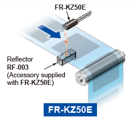
| Narrow beam | Top sensing | FR-KZ50H | 20 to 300 0.787 to 11.811 | 20 to 1,000 0.787 to 39.370 | 20 to 400 0.787 to 15.748 | 20 to 200 0.787 to 7.874 | 20 to 200 0.787 to 7.874 |
| Side sensing | FR-KZ50E | 20 to 300 0.787 to 11.811 | 20 to 1,000 0.787 to 39.370 | 20 to 400 0.787 to 15.748 | 20 to 200 0.787 to 7.874 | 20 to 200 0.787 to 7.874 | |
Note1:Note that the sensing range of the free-cut type fiber may be reduced by 20 % max. depending upon how the fiber is cut.
Note2:The sensing range is the possible setting range for the attached reflector. The fiber can detect an object less than setting range for the reflector.
■Reflective type
| Type | Sensing range(mm in) (Note1)(Note2) | |||||
|---|---|---|---|---|---|---|
| STD | H-PWR | LONG | FAST | H-SPD | ||
| Long range | FD-Z50HW | 10 to 650 0.394 to 25.591 | 10 to 2,500 0.394 to 98.425 | 10 to 1,000 0.394 to 39.370 | 10 to 410 0.394 to 16.142 | 15 to 130 0.591 to 5.118 |
Note1:Note that the sensing range of the free-cut type fiber may be reduced by 20 % max. depending upon how the fiber is cut.
Note2:The sensing range of reflective type is specified for white non-glossy paper.
For details of Narrow Beam Fiber, refer to product information page.
>>Go to "Narrow Beam Fiber"
Wide Beam
■Thru-beam type (one pair set)
| Type | Model No. | Sensing range(mm in) (Note1) | ||||
|---|---|---|---|---|---|---|
| STD | H-PWR | LONG | FAST | H-SPD | ||
| Wide beam | FT-A32 | 3,600 141.732 (Note2) | 3,600 141.732 (Note2) | 3,600 141.732 (Note2) | 3,600 141.732 (Note2) | 2,100 82.677 |
| FT-A32W | 3,600 141.732 (Note2) | 3,600 141.732 (Note2) | 3,600 141.732 (Note2) | 3,600 141.732 (Note2) | 3,000 118.110 | |
| FT-A11 | 3,600 141.732 (Note2) | 3,600 141.732 (Note2) | 3,600 141.732 (Note2) | 3,600 141.732 (Note2) | 1,100 43.307 | |
| FT-A11W | 3,600 141.732 (Note2) | 3,600 141.732 (Note2) | 3,600 141.732 (Note2) | 3,600 141.732 (Note2) | 1,300 51.181 | |
| Array | FT-AL05 | 860 33.858 | 2,300 90.551 | 1,500 59.055 | 500 19.685 | 170 6.693 |
Note1:Note that the sensing range of the free-cut type fiber may be reduced by 20 % max. depending upon how the fiber is cut.
Note2:The fiber cable length practically limits the sensing range.
>>Go to "Wide Beam Fiber"
■Reflective type
| Type | Model No. | Sensing range(mm in) (Note1)(Note2) | ||||
|---|---|---|---|---|---|---|
| STD | H-PWR | LONG | FAST | H-SPD | ||
| Wide beam | FD-A16 | 200 7.874 | Cannot use | 200 7.874 | 140 5.512 | 75 2.953 |
| Array | FD-AL12 | 270 10.630 | 670 26.378 | 420 16.535 | 150 5.906 | 50 1.969 |
Note1:Note that the sensing range of the free-cut type fiber may be reduced by 20 % max. depending upon how the fiber is cut.
Note2:The sensing range is specified for white non-glossy paper.
For details of Wide Beam Fiber, refer to product information page.
>>Go to "Wide Beam Fiber"
Convergent Reflective Type
■Reflective type
| Type | Model No. | Sensing range(mm in) (Note1)(Note2) | ||||
|---|---|---|---|---|---|---|
| STD | H-PWR | LONG | FAST | H-SPD | ||
| Glass substrate detection | FD-L32H | 0 to 56 0 to 2.205 | 0 to 110 0 to 4.331 | 0 to 74 0 to 2.913 | 1 to 38 0.039 to 1.496 | Cannot use |
| FD-L30A | 0 to 43 0 to 1.693 | 0 to 43 0 to 1.693 | 0 to 43 0 to 1.693 | 0 to 42 0 to 1.654 | 0 to 29 0 to 1.142 | |
| FD-L31A | 4 to 33 0.157 to 1.299 | 3 to 35 0.118 to 1.378 | 4 to 33 0.157 to 1.299 | 4 to 32 0.157 to 1.260 | 5 to 25 0.197 to 0.984 | |
| FD-L24A | 0 to 23 0 to 0.906 | 0 to 31 0 to 1.220 | 0 to 26 0 to 1.024 | 0 to 22 0 to 0.866 | 0 to 18 0 to 0.709 | |
| FD-L25 | 0 to 29 0 to 1.142 | 0 to 30 0 to 1.181 | 0 to 30 0 to 1.181 | 0 to 28 0 to 1.102 | 2 to 23 0.079 to 0.906 | |
| FD-L11 | 0 to 9.5 0 to 0.374 | 0 to 11.5 0 to 0.453 | 0 to 10 0 to 0.394 | 0 to 9 0 to 0.354 | 0 to 8 0 to 0.315 | |
| FD-L10 | 0 to 5 0 to 0.197 | 0 to 6 0 to 0.236 | 0 to 5.5 0 to 0.217 | 0 to 4.5 0 to 0.177 | 0 to 4 0 to 0.157 | |
| FD-L21 | 1.5 to 16 0.059 to 0.630 | 1 to 19 0.039 to 0.748 | 1 to 18 0.039 to 0.709 | 2 to 15 0.079 to 0.591 | 3 to 12 0.118 to 0.472 | |
| FD-L21W | 3 to 14 0.118 to 0.551 | 1.5 to 15 0.059 to 0.591 | 2 to 15 0.079 to 0.591 | 4 to 14 0.157 to 0.551 | 6.5 to 10 0.256 to 0.394 | |
| General purpose | FD-L20H | 0 to 23 0 to 0.906 | 0 to 45 0 to 1.772 | 0 to 32 0 to 1.260 | 2 to 15 0.079 to 0.591 | 5 to 9 0.197 to 0.354 |
| Ultla-small | FD-L12W | 0 to 8 0 to 0.315 | 0 to 14 0 to 0.551 | 0 to 12 0 to 0.472 | 0.5 to 7 0.020 to 0.276 | 0.5 to 4 0.020 to 0.157 |
| FD-L13H1 | 0 to 4 0 to 0.157 | 0 to 5 0 to 0.197 | 0 to 4 0 to 0.157 | 0 to 3.5 0 to 0.138 | 0 to 2 0 to 0.079 | |
Note1:The sensing range is specified for transparent glass 100 x 100 x t0.7 mm 3.937 × 3.937 × t0.028 in (FD-L32H: R edge, FD-L21 and FD-L21W: t2 mm t0.079 in, FD-L13H1: 50 × 50 × t0.7 mm 1.969 × 1.969 × t0.028 in.) (FD-L20H: white non-glossy paper, FD-L10: silicon wafers 100 x 100 mm 3.937 × 3.937 in).
Note2:Note that the sensing range of the free-cut type fiber may be reduced by 20 % max. depending upon how the fiber is cut.
For details of Convergent Reflective Type Fiber, refer to product information page.
>>Go to "Convergent Reflective Type Fiber"
Retroreflective Type
■Retroreflective type
| Type | Model No. | Sensing range(mm in) (Note1)(Note2) | |||||
|---|---|---|---|---|---|---|---|
| STD | H-PWR | LONG | FAST | H-SPD | |||
| With polarizing filters | FR-Z50HW | 100 to 990 3.937 to 38.976 | 100 to 1,900 3.937 to 74.803 | 100 to 1,200 3.937 to 47.244 | 100 to 780 3.937 to 30.709 | 100 to 490 3.937 to 19.291 | |
| Ultra-narrow beam | FR-KZ22E | 15 to 310 0.591 to 12.205 | 15 to 570 0.591 to 22.441 | 15 to 410 0.591 to 16.142 | 15 to 220 0.591 to 8.661 | 15 to 100 0.591 to 3.937 | |
| Narrow beam | Top sensing | FR-KZ50H | 20 to 300 0.787 to 11.811 | 20 to 1,000 0.787 to 39.370 | 20 to 400 0.787 to 15.748 | 20 to 200 0.787 to 7.874 | 20 to 200 0.787 to 7.874 |
| Side sensing | FR-KZ50E | 20 to 300 0.787 to 11.811 | 20 to 1,000 0.787 to 39.370 | 20 to 400 0.787 to 15.748 | 20 to 200 0.787 to 7.874 | 20 to 200 0.787 to 7.874 | |
Note1:Note that the sensing range of the free-cut type fiber may be reduced by 20 % max. depending upon how the fiber is cut.
Note2:The sensing range is the possible setting range for the attached reflector. The fiber can detect an object less than setting range for the reflector.
For details of Retroreflective Type Fiber, refer to product information page.
>>Go to "Retroreflective Type Fiber"
Chemical-resistant
■Thru-beam type (one pair set)
| Type | Model No. | Sensing range(mm in) (Note1) | ||||
|---|---|---|---|---|---|---|
| STD | H-PWR | LONG | FAST | H-SPD | ||
| Chemical-resistant | FT-Z802Y | 3,100 122.047 | 3,600 141.732 (Note2) | 3,600 141.732 (Note2) | 1,900 74.803 | 470 18.504 |
| FT-HL80Y (Discontinued products) | 3,600 141.732 (Note2) | 3,600 141.732 (Note2) | 3,600 141.732 (Note2) | 2,300 90.551 | 740 29.134 | |
| FT-L80Y | 3,600 141.732 (Note2) | 3,600 141.732 (Note2) | 3,600 141.732 (Note2) | 2,800 110.236 | 920 36.220 | |
| FT-V80Y | 1,300 51.181 | 3,600 141.732 (Note2) | 2,200 86,614 | 800 31,496 | 240 9,449 | |
Note1:Note that the sensing range of the free-cut type fiber may be reduced by 20 % max. depending upon how the fiber is cut.
Note2:The fiber cable length practically limits the sensing range.
■Reflective type
| Type | Model No. | Sensing range(mm in)(Note1)(Note2) | ||||
|---|---|---|---|---|---|---|
| STD | H-PWR | LONG | FAST | H-SPD | ||
| Chemical-resistant | FD-S60Y | 320 12.598 | 600 23.622 | 420 16.535 | 200 7.874 | 75 2.953 |
Note1:Note that the sensing range of the free-cut type fiber may be reduced by 20 % max. depending on how the fiber is cut.
Note2:The sensing range is specified for white non-glossy paper.
For details of Chemical-resistant Fiber, refer to product information page.
>>Go to "Chemical-resistant Fiber"
Heat-resistant
■Thru-beam type (one pair set)
| Type | Heat-resistant temp. | Model No. | Sensing range(mm in) (Note1) | ||||
|---|---|---|---|---|---|---|---|
| HYPR | U-LG | LONG | STD | FAST | |||
| Heat-resistant | 350℃ | FT-H35-M2 | 430 16.929 | 1,200 47.244 | 670 26.378 | 250 9.843 | 80 3.150 |
| FT-H35-M2S6 | 430 16.929 | 1,200 47.244 | 670 26.378 | 250 9.843 | 80 3.150 | ||
| 200℃ | FT-H20W-M1 | 470 18.504 | 1,600 62.992 (Note2) | 840 33.071 | 300 11.811 | 90 3.543 | |
| FT-H20-M1 | 540 21.260 | 1,600 62.992 (Note2) | 960 37.795 | 330 12.992 | 110 4.331 | ||
| 130℃ | FT-H13-FM2 | 700 27.559 | 3,300 129.921 | 1,300 51.181 | 410 16.142 | 140 5.512 | |
| Heat-resistant (joint) | 200℃ | FT-H20-J20-S | 470 18.504 | 1,600 62.992 | 790 31.102 | 300 11.811 | 90 3.543 |
| FT-H20-J30-S | 470 18.504 | 1,600 62.992 | 790 31.102 | 300 11.811 | 90 3.543 | ||
| FT-H20-J50-S | 470 18.504 | 1,600 62.992 | 790 31.102 | 300 11.811 | 90 3.543 | ||
| FT-H20-VJ50-S | 600 23.622 | 2,100 82.677 | 980 38.583 | 390 15.354 | 120 4.724 | ||
| FT-H20-VJ80-S | 600 23.622 | 2,100 82.677 | 980 38.583 | 390 15.354 | 120 4.724 | ||
Note1:Note that the sensing range of the free-cut type fiber may be reduced by 20 % max. depending upon how the fiber is cut.
Note2:The fiber cable length practically limits the sensing range.
■Reflective type
| Type | Heat-resistant temp. | Model No. | Sensing range(mm in) (Note1)(Note2) | |||||
|---|---|---|---|---|---|---|---|---|
| STD | H-PWR | LONG | FAST | H-SPD | ||||
| Heat-resistant | Threaded | 350℃ | FD-H35-M2 | 260 10.236 | 720 28.346 | 460 18.110 | 150 5.906 | 45 1.772 |
| FD-H35-M2S6 | 260 10.236 | 720 28.346 | 460 18.110 | 150 5.906 | 45 1.772 | |||
| FD-H35-20S | 260 10.236 | 840 33.071 | 440 17.323 | 140 5.512 | 45 1.772 | |||
| 200℃ | FD-H20-M1 | 330 12.992 | 840 33.071 | 500 19.685 | 200 7.874 | 55 2.165 | ||
| FD-H20-21 | 230 9.055 | 770 30.315 | 380 14.961 | 130 5.118 | 45 1.772 | |||
| 130℃ | FD-H13-FM2 | 350 13.780 | 880 34.646 | 600 23.622 | 200 7.874 | 65 2.559 | ||
| Glass substrate detection convergent reflective | 300℃ | FD-H30-L32 | 0 to 17 0 to 0.669 | 0 to 40 0 to 1.575 | 0 to 25 0 to 0.984 | 0 to 12 0 to 0.472 | 1.5 to 6 0.059 to 0.236 | |
| 250℃ | FD-H25-L43 | 1.5 to 26 0.059 to 1.024 | 1 to 31 0.039 to 1.220 | 1 to 28 0.039 to 1.102 | 1.5 to 24 0.059 to 0.945 | 2 to 18 0.079 to 0.709 | ||
| FD-H25-L45 | 5 to 42 0.197 to 1.654 | 4 to 43.5 0.157 to 1.713 | 4.5 to 43 0.177 to 1.693 | 5 to 40 0.197 to 1.575 | 6.5 to 34 0.256 to 1.339 | |||
| 180℃ | FD-H18-L31 | 0 to 16 0 to 0.630 | 0 to 60 0 to 2.362 | 0 to 24 0 to 0.945 | 0 to 13 0 to 0.512 | 2 to 6.5 0.079 to 0.256 | ||
Note1:The sensing range of reflective type is the value for white non-glossy paper (50 x 50 mm 1.969 × 1.969 in glass substrate for FD-H30-L32 and FD-H18-L31, transparent glass 100 x 100 x t0.7 mm 3.937 × 3.937 × t0.028 in for FD-H25-L43 and FD-H25-L45).
Note2:Note that the sensing range of the free-cut type fiber may be reduced by 20 % max. depending upon how the fiber is cut.
For details of Heat-resistant Fiber, refer to product information page.
>>Go to "Heat-resistant Fiber"
One-Touch Connection System Vacuum-resistant Fibers
■Thru-beam type
| Type | Model No. | Sensing range (mm in)(Note1) | |||||
|---|---|---|---|---|---|---|---|
| STD | H-PWR | LONG | FAST | H-SPD | |||
| Vacuum- resistant | Thru-beam | FT-40V | 270 10.630 | 1,000 39.370 | 470 18.504 | 160 6.299 | 55 2.165 |
Note1:Atmospheric side fiber, FT-J9 (optional) is free-cut type.
Note that the sensing range of the free-cut type fiber may be reduced by 20 % max. depending upon how the fiber is cut.
■Reflective type
| Type | Model No. | Sensing range(mm in) (Note1)(Note2) | |||||
|---|---|---|---|---|---|---|---|
| STD | H-PWR | LONG | FAST | H-SPD | |||
| Vacuum- resistant | Long range reflective | FD-KZ50V | 20 to 200 0.787 to 7.874 | 5 to 500 0.197 to 19.685 | 15 to 270 0.591 to 10.630 | 20 to 120 0.787 to 4.724 | 20 to 45 0.787 to 1.772 |
| Convergent reflective | FD-L10V | 0 to 8 0 to 0.315 | 0 to 18 0 to 0.709 | 0 to 10 0 to 0.394 | 0 to 5.5 0 to 0.217 | 1.5 to 3 0.059 to 0.118 | |
Note1:The sensing range is the value for transparent glass 100 × 100 × t0.7 mm 3.937 × 3.937 × t0.028 in.
Note2:Atmospheric side fiber, FT-J9 (optional) is free-cut type.
Note that the sensing range of the free-cut type fiber may be reduced by 20 % max. depending upon how the fiber is cut.
For details of One-Touch Connection System Vacuum-resistant Fibers, refer to product information page.
>>Go to "One-Touch Connection System Vacuum-resistant Fibers"
Vacuum-resistant
■Thru-beam type (one pair set)
| Type | Model No. | Sensing range(mm in) | |||||
|---|---|---|---|---|---|---|---|
| STD | H-PWR | LONG | FAST | H-SPD | |||
| Vacuum-resistant | Thru-beam | FT-H30-M1V-S | 270 10.630 | 1,000 39.370 | 470 18.504 | 160 6.299 | 55 2.165 |
■Reflective type
| Type | Model No. | Sensing range(mm in) (Note1) | |||||
|---|---|---|---|---|---|---|---|
| STD | H-PWR | LONG | FAST | H-SPD | |||
| Vacuum-resistant | Reflective | FD-H30-KZ1V-S | 20 to 200 0.787 to 7.874 | 5 to 500 0.197 to 19.685 | 15 to 270 0.591 to 10.630 | 20 to 120 0.787 to 4.724 | 20 to 45 0.787 to 1.772 |
| Convergent reflective | FD-H30-L32V-S | 0 to 8 0 to 0.315 | 0 to 18 0 to 0.709 | 0 to 10 0 to 0.394 | 0 to 5.5 0 to 0.217 | 1.5 to 3 0.059 to 0.118 | |
Note1:The sensing range of reflective type is the value for transparent glass 100 x 100 x t0.7 mm 3.937 × 3.937 × t0.028 in.
For details of Vacuum-resistant Fiber, refer to product information page.
>>Go to "Vacuum-resistant Fiber"
Special-shaped fiber

| Model No. | Sensing range (mm in) (Note) | |||||
|---|---|---|---|---|---|---|
| STD | H-PWR | LONG | FAST | H-SPD | ||
| Heat-resistant U-shaped type | FT-PK40H1 | 5 0.197(fixed) | 5 0.197(fixed) | 5 0.197(fixed) | 5 0.197(fixed) | 5 0.197(fixed) |
Note:Note that the sensing range of the free-cut type fiber may be reduced by 20 % max. depending upon how the fiber is cut.
For details of Special-shaped fiber, refer to product information page.
>>Go to "Special-shaped fiber"